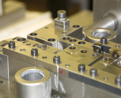
Pipe Fabrication Drawings: Definition and Purpose
Pipe fabrication drawings are highly detailed technical documents used to guide the precise manufacturing, assembly, and installation of piping systems in industrial projects such as oil and gas facilities, chemical plants, and HVAC systems. These drawings serve as the “blueprint” for fabricators, welders, and assembly teams, ensuring that each pipe section and component is built and assembled to exact specifications.
Key Features of Pipe Fabrication Drawings:
- Detailed Measurements:
Fabrication drawings provide exact dimensions (often to millimeter precision) for pipes, fittings, and components, including lengths, diameters, and angles. - Component Specifications:
They specify materials, wall thickness, pipe schedules, and any special treatments or finishes required for each part. - Welding and Assembly Instructions:
These drawings include welding symbols, type of joints (butt, socket, threaded), bolt sizes, hole locations, and detailed assembly sequences. - Tolerances and Quality Requirements:
Information on allowable tolerances, machining requirements, and quality standards is provided to ensure components fit and function as designed. - Isometric and Orthographic Views:
Pipe fabrication drawings often use isometric views to show the three-dimensional routing of pipes, making it easier to visualize complex assemblies. Orthographic views (top, side, front) may also be included for clarity.
Who Uses Pipe Fabrication Drawings?
- Fabricators and welders in workshops or factories
- Machine operators and assembly teams
- Quality assurance inspectors
- Suppliers of prefabricated piping systems
Purpose and Importance:
- Guidance for Fabrication:
They provide all the necessary information for cutting, welding, and assembling Pipe Spool Shop Drawings and components before installation. - Accuracy and Consistency:
Ensure that all fabricated parts meet design intent and fit together correctly on-site, minimizing errors and rework. - Coordination:
Help coordinate fabrication with other disciplines (e.g., structural, electrical), ensuring smooth integration during construction.
| Feature | Description |
|---|---|
| Dimensions | Precise measurements for cutting and assembly |
| Specifications | Material, wall thickness, and special treatments |
| Welding/Assembly | Symbols, joint types, bolt/hole locations, assembly sequences |
| Views | Isometric (3D) and orthographic (2D) for clear visualization |
| Users | Fabricators, welders, QA inspectors, suppliers |
| Purpose | Guide accurate manufacturing and assembly of piping systems |
Pipe fabrication drawings are essential for turning engineering designs into physical piping systems, ensuring safety, quality, and efficiency throughout the construction process.
For more information, or to hire an experienced Pipe Fabrication Drawing firm, contact us here: Advantage Engineering or by Tel: (518) 320-2501

