HVAC Coordination Drawings are detailed, BIM-driven construction documents that align HVAC ductwork, piping, and equipment with structural, architectural, electrical, plumbing, and fire protection systems. They eliminate clashes, improve installation accuracy, and ensure all trades can build from a coordinated, constructible layout.
Modern commercial and industrial construction leaves zero room for field improvisation. Tight ceiling spaces, congested mechanical rooms, aggressive schedules, and submitted equipment substitutions that routinely invalidate spatial assumptions — these are the realities HVAC contractors live with every day. When the coordination model was built around the design engineer’s generic equipment and the submitted unit shows up three inches deeper, that gap comes out of the ceiling plenum.
HVAC Coordination Drawings are the tool that resolves those conflicts before they reach the job site. At Advantage Engineering Technologies (AET), we specialize in BIM-driven HVAC coordination for mechanical and plumbing contractors working on healthcare, institutional, and complex commercial projects. Our PE-stamped background and construction-phase BIM experience means we understand what contractors actually need from a coordination package — not just a model, but constructible, field-ready drawings.
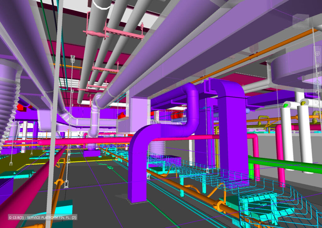
Above-ceiling MEP coordination model — HVAC, mechanical piping, electrical, plumbing, and fire protection resolved before first piece of ductwork arrives on site.
Why HVAC Coordination Drawings Matter for Contractors
Construction spaces are getting tighter and project schedules are getting shorter. Without proper coordination, contractors face hard costs that show up as change orders, schedule extensions, and rework labor. The problems we see most frequently on healthcare and institutional projects include:
- Ductwork hitting structural beams due to slab depth assumptions that didn’t account for actual beam flange width
- VAV boxes conflicting with sprinkler mains when submitted unit dimensions differ from design model geometry
- Condensate piping crossing electrical conduit in congested above-ceiling corridors
- Access panels blocked by architectural soffits installed before coordination was completed
- Hanger rod conflicts with duct flanges in tight shaft conditions
- Sleeve sizes set to design pipe OD without accounting for insulation clearance, discovered at pour
- Equipment clearances violated by adjacent trades routing around uncoordinated HVAC elements
Coordination Drawings eliminate these issues before they reach the job site — digitally, in the model, where changes cost hours instead of days.
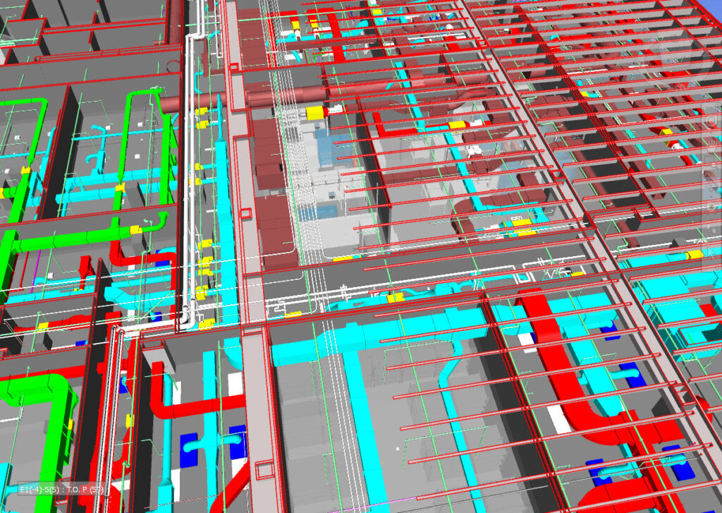
Full-floor MEP coordination model with roof structure removed — all trades integrated and clash-tested prior to fabrication.
Key Benefits of HVAC Coordination Drawings
- Minimize Field Clashes and Rework
Clashes are identified and resolved digitally — long before fabrication or installation. Every hour spent resolving a conflict in the model eliminates multiple hours of field rework and avoids the RFI cycle that costs everyone time.
- Improve Installation Accuracy
Contractors receive dimensioned, elevation-verified layouts that field crews can install with confidence. TOD/BOD elevations, hanger spacing, and offset geometry are defined before the first piece of iron goes up.
- Protect the Schedule
Coordinated drawings prevent last-minute redesigns and emergency RFIs that stall subcontractor crews. When submitted equipment substitutions arrive mid-project, the model is updated and re-coordinated before installation proceeds — not discovered in the ceiling.
- Optimize Space Utilization
Critical in hospitals, data centers, surgery centers, and university buildings where ceiling plenum space is the most contested real estate on the project. Coordination determines who goes where — and documents it.
- Enhance Multi-Trade Communication
All disciplines work from the same coordinated model. Conflicts become coordination meeting agenda items rather than field surprises. Structural openings, sleeve locations, and equipment clearances are confirmed by all trades before work begins.
- Improve Budgeting and Change Order Defense
When coordination is documented in the model, contractors have a clear record of what was designed, what was submitted, and how routing decisions were made. That paper trail matters when change order disputes arise.
What’s Included in AET’s HVAC Coordination Packages
Our coordination packages are built for mechanical and plumbing contractors who need construction-grade detail, not design-intent placeholders. A typical AET coordination package includes:
- Duct routing with TOD/BOD elevations, offsets, and transition geometry
- VAV/FPB box locations with access clearance zones confirmed against submitted equipment dimensions
- Mechanical piping layouts (CHW, HW, CW, CD, refrigerant) with insulation clearances applied
- Hanger and support locations, including trapeze sizing where applicable
- Sleeve and penetration drawings coordinated to actual installed pipe OD plus insulation
- Equipment coordination (AHUs, RTUs, FCUs, ERVs) based on approved submittals, not design model stubs
- Mechanical room coordination with maintenance clearances enforced
- Above-ceiling coordination with all trades integrated
- Dimensioned installation drawings for field crews
This is the level of detail HVAC contractors need to install confidently and defend their work when conditions deviate from design.
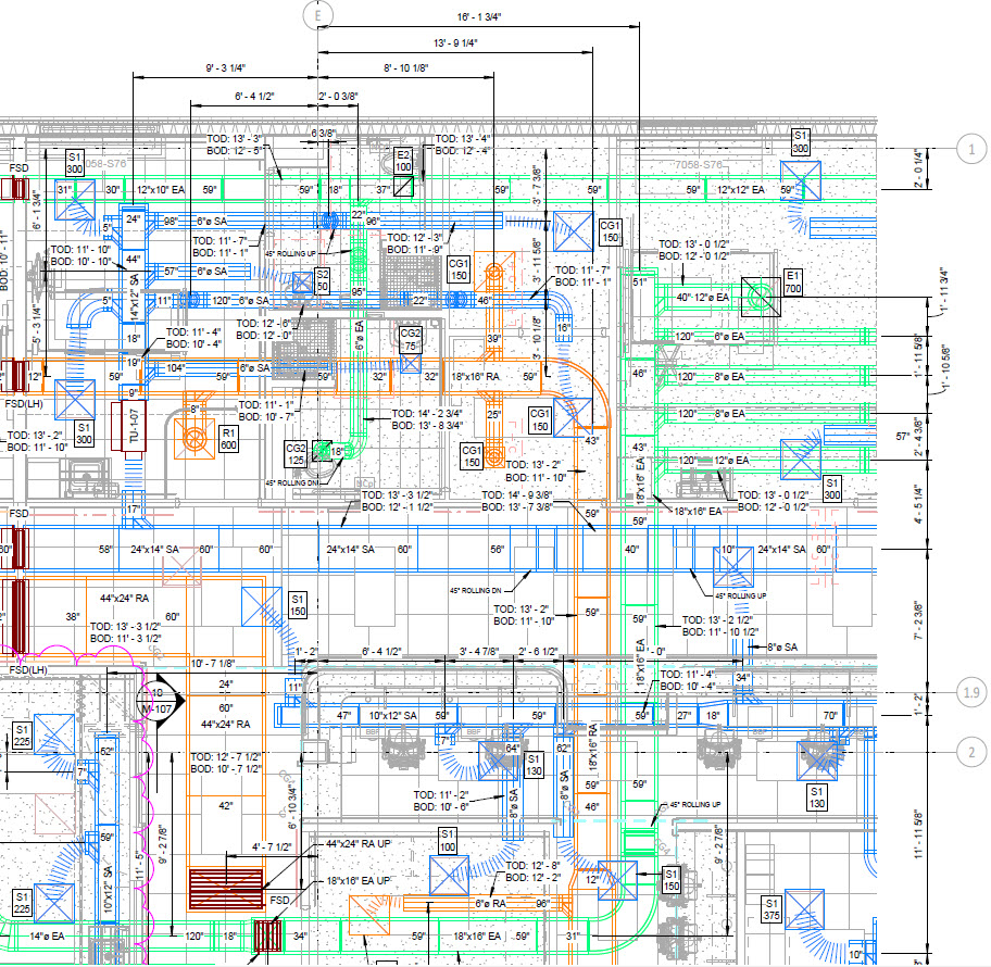
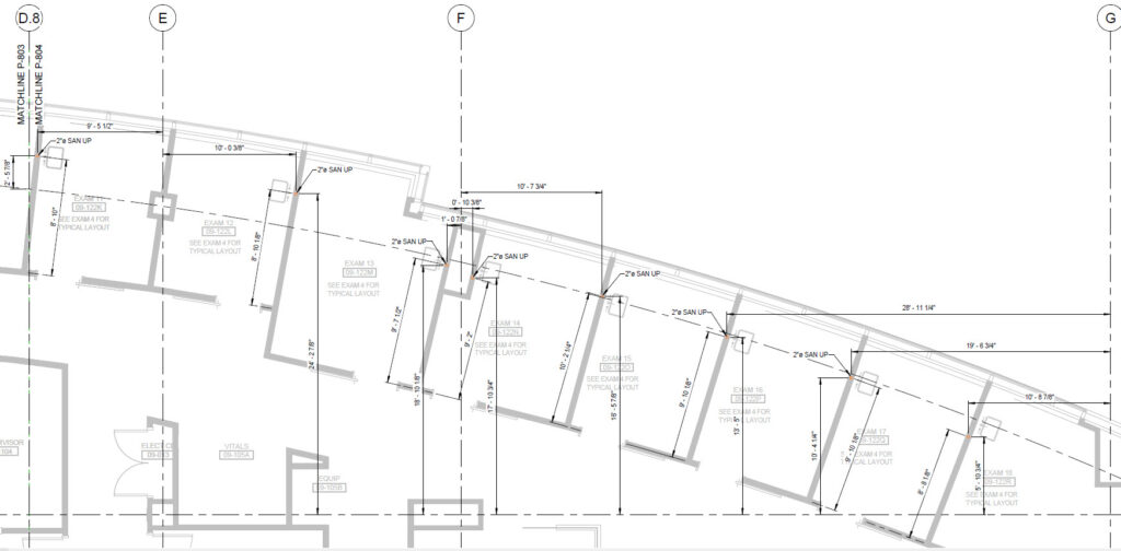
Contractor-grade HVAC duct coordination drawing — Harrison Hospital project. TOD/BOD elevations, duct sizes, VAV terminal unit locations, and FSD placements fully dimensioned for field installation.
Common Clash Types Resolved During Coordination
Not all clashes are created equal. Experienced contractors know that the most expensive clashes are the ones that look minor in the model:
- Duct vs. structural beam (including lateral brace conditions often missing from structural BIM exports)
- VAV box vs. sprinkler main (especially when submitted VAV unit is physically larger than design model)
- Condensate piping vs. electrical conduit in congested corridor ceilings
- Duct transitions conflicting with recessed lighting fixtures and fire sprinkler heads
- AHU and FCU access panel clearance violations against adjacent ductwork and piping
- Mechanical piping crossing plumbing stacks and vents
- Hanger rod conflicts with duct flanges and pipe insulation in shaft conditions
- Sleeve centerlines shifted by concrete formwork changes, discovered after pour
BIM coordination identifies these conflicts early and resolves them collaboratively — before the foreman finds them with a tape measure.
How HVAC Coordination Drawings Support BIM Workflows
Today’s complex construction projects rely on Building Information Modeling (BIM) as the backbone of trade coordination. But BIM is only as valuable as the quality of content it contains. Design models built with standard Revit system families — without fabrication-level geometry, insulation, or construction-accurate connections — cannot serve as coordination models without significant rework.
AET builds coordination models using MEP Fabrication content (ESTmep/CADmep catalog geometry) where required, ensuring that what you see in the model is what you actually install — including insulation thicknesses, hanger attachments, and fitting geometry. The advantages of this approach include:
- Accurate 3D visualization reflecting actual installed conditions, not design intent
- LOD 300/350/400 development matched to project phase and contractor need
- Clash detection that catches real interference, not phantom conflicts from under-detailed model content
- Design validation against approved submittals before fabrication begins
- Better communication with GCs, structural, and other trades during coordination meetings
- Model accuracy that supports facility management handover when the project closes out
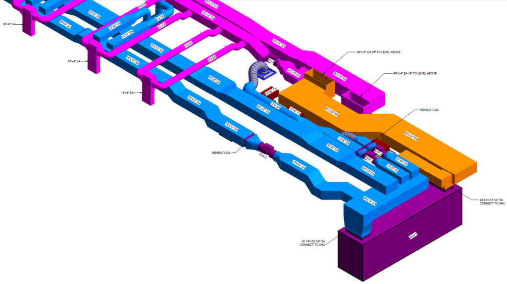
Revit ductwork isometric — WVU Health Sciences Center project. Supply, return, exhaust, and OA systems fully labeled and coordinated at LOD 350 prior to fabrication.
The AET HVAC Coordination Workflow
Step 1 — Model Development (LOD 300–350)
We build detailed HVAC BIM models using design documents, approved equipment submittals, and contractor input. Submitted equipment dimensions are incorporated before coordination begins — not treated as a future revision.
Step 2 — Multi-Trade Model Integration
We combine HVAC with structural, architectural, electrical, plumbing, and fire protection models. Where trade models are incomplete or use under-detailed content, we flag it before running clash detection rather than generating false-positive results.
Step 3 — Clash Detection (Navisworks / BIM 360)
We run systematic clash tests covering hard clashes, soft clashes (clearance violations), and access conflicts. Results are filtered and triaged — not delivered as a raw list of 3,000 items that includes duct insulation touching pipe insulation.
Step 4 — Coordination Meetings and Resolution
Conflicts are resolved through structured coordination meetings, trade-by-trade model reviews, routing adjustments, elevation changes, and equipment repositioning. AET participates actively in coordination meetings as a technical resource, not just a model manager.
Step 5 — Final Coordination Drawings (LOD 350–400)
We produce plan views, section views, elevation views, and detailed installation drawings at the level of detail your field crews can install from without additional interpretation.
Step 6 — Installation Support
Field teams receive dimensioned layouts, hanger locations, sleeve drawings, and RFI support. Where conditions deviate from the model during construction, we update the coordination drawings to reflect field conditions.
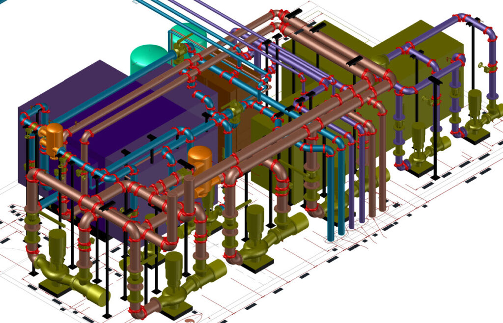
Mechanical room BIM model — Whole Foods Market project. Complete piping layout with valves, pumps, strainers, and connections modeled at LOD 350 for fabrication and coordination.
HVAC Coordination Drawings vs. HVAC Shop Drawings
Contractors frequently ask how coordination drawings and shop drawings relate. The answer depends on project phase and purpose:
| Feature | HVAC Coordination Drawings | HVAC Shop Drawings |
| Purpose | Multi-trade clash resolution | Fabrication & installation |
| BIM LOD | LOD 300–350 | LOD 350–400 |
| Clash Detection | Extensive — all trades | Limited — within discipline |
| Project Stage | Pre-construction coordination | Construction / fabrication |
| Model Content | All MEP + structural + arch | HVAC system detail only |
| Output | Constructible, coordinated layouts | Fabrication-ready component details |
| Who Uses It | GC, all trade contractors | Sheet metal fabricator, field crew |
Contractors typically need both — coordination drawings first to establish the constructible routing, shop drawings second to fabricate and install from. AET delivers both as part of an integrated workflow.
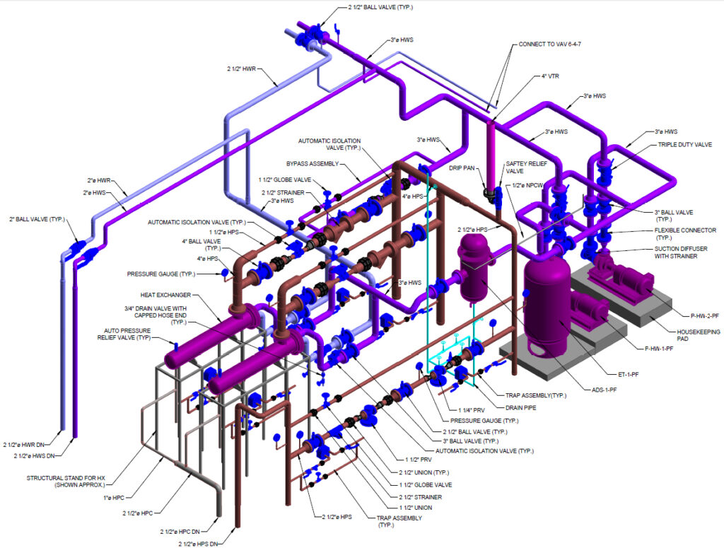
Mechanical room isometric shop drawing — complete valve schedule, equipment tags, and piping callouts produced directly from coordinated BIM model for contractor installation.
BIM Services for HVAC Contractors: The Competitive Advantage
Contractors who incorporate BIM coordination into their pre-construction process gain measurable advantages on complex projects:
- Earlier identification of schedule risks tied to coordination gaps
- Reduced installation errors and associated rework labor costs
- Higher fabrication accuracy when shop drawings are produced from a validated coordination model
- Faster project delivery by eliminating coordination surprises during construction
- Lower overall project costs through reduced change orders and field modifications
- Stronger competitive position on bid proposals for BIM-required projects
AET provides end-to-end BIM services tailored specifically for mechanical and plumbing contractors — from coordination through as-built documentation. We are not a VDC production shop staffed with CAD operators; we are a PE-licensed engineering firm that understands what the model needs to do in the field.
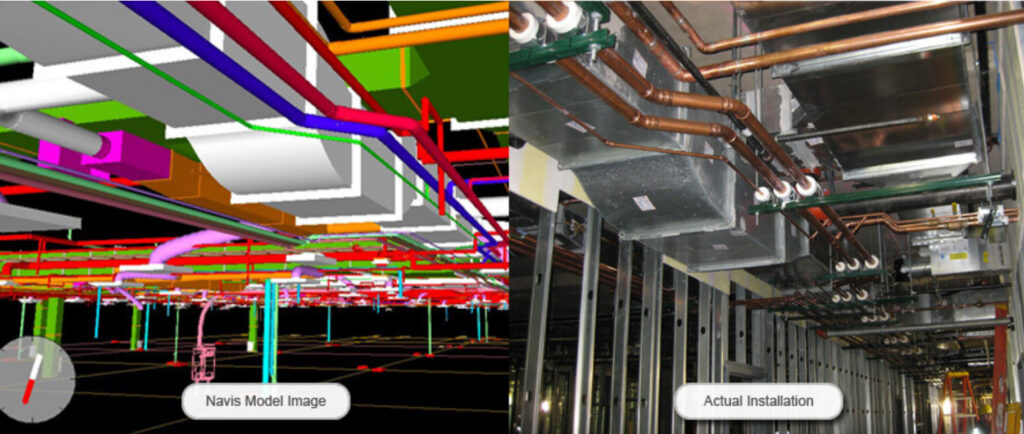
BIM coordination model (left) vs. actual field installation (right) — model-to-construction accuracy achieved through AET’s BIM coordination and shop drawing process.
The Role of HVAC As-Built Modeling
Red-line markups on paper drawings are the traditional as-built deliverable — and they are nearly useless for facility management. A set of field redlines that documents “make or break” deviations without updated model geometry leaves the owner with no reliable record of what is actually in the ceiling.
After installation, AET delivers true as-built BIM models based on field markups, construction photographs, and laser scans where available. These models support:
- Facility management and preventive maintenance planning
- Future renovation and addition projects with accurate existing conditions
- Maintenance planning with confirmed equipment locations and access paths
- Asset tracking tied to actual installed equipment tags and serial numbers
- Reduced operational risk when systems require emergency modification
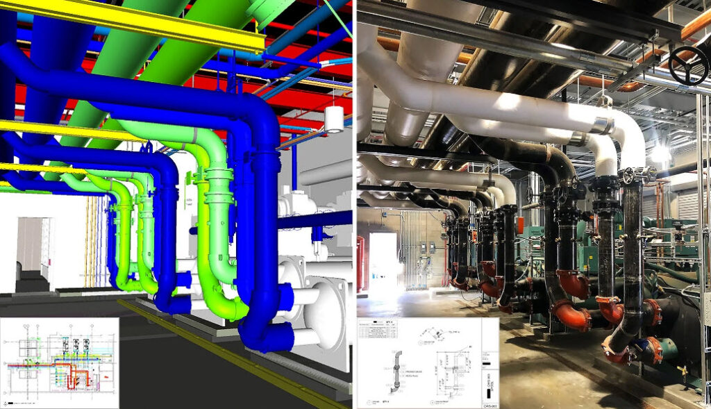
Chiller plant BIM model (left) vs. completed field installation (right) — AET as-built modeling captures installed conditions with PE-verified accuracy for long-term facility use.
BIM for Commercial and Healthcare HVAC Systems
The value of BIM coordination scales with project complexity. AET’s experience includes coordination on:
- Healthcare facilities and hospital renovations — where infection control zones, surgical suite pressurization, and occupied adjacent spaces make field improvisation unacceptable
- Data centers and mission-critical facilities — where ceiling space is consumed by redundant infrastructure and there is no margin for rerouting
- University and research buildings — with laboratory exhaust, specialty gas, and complex mechanical interplay
- Office and commercial buildings — where tenant-driven ceiling height requirements make every inch of plenum space contested
- Industrial and manufacturing facilities — with process piping, compressed air, and specialty ventilation integrated with structural steel
BIM coordination ensures these systems are constructible, efficient, and maintainable — from the pre-construction model through facility turnover.
MEP pipe penetration coordination drawing — RWJBH healthcare project. Penetration locations, pipe sizes, and dimensions confirmed against structural drawings and coordinated with all trades.
People Also Ask
What are HVAC Coordination Drawings used for?
They coordinate HVAC systems with other trades in a shared BIM environment, identify and resolve physical conflicts before installation, and produce constructible layouts that field crews can install without field-engineering the routing themselves.
How do HVAC Coordination Drawings reduce project costs?
By resolving conflicts digitally before fabrication, contractors eliminate costly field rework, avoid schedule delays caused by trade conflicts, and reduce RFI volume. The cost of coordination is typically a fraction of the cost of a single rework event on a congested healthcare corridor.
Are HVAC Coordination Drawings required for BIM projects?
On BIM-required projects (most healthcare, institutional, and large commercial work), coordination drawings are a contract deliverable. On projects without a BIM mandate, forward-thinking contractors use them proactively to protect their schedule and budget.
What is the difference between HVAC BIM Modeling and HVAC Coordination Drawings?
BIM Modeling creates the 3D model. Coordination Drawings use that model to produce the construction-ready deliverable — plan views, section views, elevations, and dimensioned layouts that the field crew installs from. The model is the process; the coordination drawings are the product.
What LOD are HVAC Coordination Drawings typically developed to?
Coordination drawings are typically developed to LOD 350, which includes sufficient geometry and component data to coordinate all trades without interference and produce fabrication-ready information. Where shop drawings are also required, the model advances to LOD 400 with full fabrication geometry.
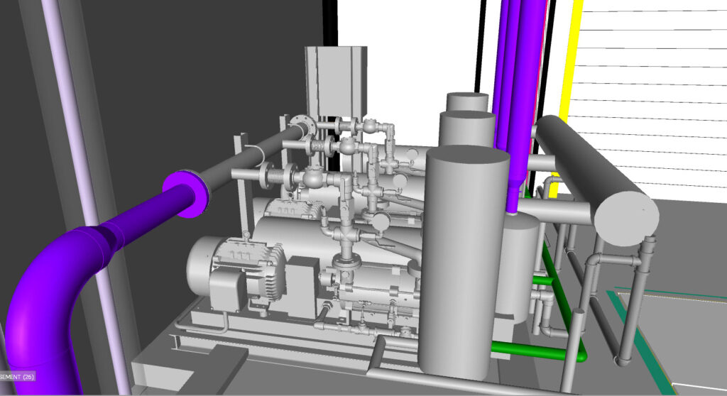
LOD 400 vacuum pump room BIM model — fabrication-accurate equipment geometry, piping connections, and service clearances modeled prior to installation.
Why Contractors Choose Advantage Engineering Technologies
AET is a PE-licensed MEP engineering firm (NY, NJ, ME) with hands-on construction-phase BIM experience. We deliver:
- HVAC Coordination Drawings developed from construction-accurate BIM models — not design-intent geometry
- HVAC BIM Modeling at LOD 300–400 using MEP Fabrication content where required
- HVAC Shop Drawings produced directly from the coordinated model
- HVAC As-Built Modeling based on field-verified conditions
- Full MEP coordination packages for mechanical and plumbing contractors
- Cognizant Engineering support on complex healthcare and institutional construction projects
We understand what happens when the submitted equipment dimensions don’t match the design model. We understand what a 2″ insulated pipe needs for hanger clearance. We know which clashes matter and which are modeling artifacts. That depth of construction-phase experience is what separates AET from a production BIM shop.
Conclusion
HVAC Coordination Drawings are not an optional add-on for complex projects — they are the mechanism that turns a design model into a constructible installation. Contractors who invest in proper BIM coordination before fabrication starts protect their schedules, reduce change order exposure, and deliver higher-quality work in tighter spaces.
If you are a mechanical or plumbing contractor working on a project that requires reliable, clash-free HVAC coordination in the Capital Region (NY), New Jersey, or Maine, Advantage Engineering Technologies is ready to support your next project.
Need fully coordinated, clash-free HVAC drawings your field team can install without delays? Contact Advantage Engineering Technologies today for BIM-driven HVAC Coordination Drawings, Shop Drawings, and complete contractor support.