
If you are bidding or building a piping scope, you are almost never the one who drew the P&IDs. They arrive from the A/E or the engineering firm the owner hired, and your job starts with a set of drawings you had no hand in producing. Everything downstream — plan views, spool drawings, cut lists, what the shop actually welds — is derived from that set.
That makes the review step worth more than it usually gets credit for. A P&ID that looks complete on paper can still be carrying conflicts that do not surface until a spool is already cut. This is what we look for, and why we look for it before anything reaches the shop.
What a P&ID Is, and What It Is Not
A Piping and Instrumentation Diagram is a schematic. It shows the functional relationships between process equipment, piping, valves, instrumentation and control devices using standardized symbols. It tells you what connects to what, in what sequence, with what controls and safety devices in the loop.
What it is not is a drawing you can build from directly. A P&ID carries no real geometry. It has no true routing, no elevations, no lengths, no orientations, no clearances. Those all have to be developed, and that development is where the conflicts appear.
| Function | What it does |
|---|---|
| Process design and planning | Establishes the layout and interconnection of plant systems |
| Operation and maintenance | Reference for operators and maintenance staff — process flow, control strategy, equipment location |
| Safety and compliance | Basis for hazard and operability studies (HAZOP) and regulatory documentation |
| Documentation | Historical record of system design and modifications, supporting management of change |
The Conflict That Costs the Most: Field Conditions and Equipment Submittals
In our experience the most expensive problems are not missing line sizes or mislabeled valves. Those get caught. The ones that reach the shop are conflicts between what the P&ID assumes and what is actually going to be installed.
Two versions of the same problem:
Submitted equipment does not match the design basis
The P&ID was developed around a basis-of-design unit. By the time the job is building, a different unit has been submitted and approved. Connection sizes, nozzle locations, orientations and required clearances may all differ from what the schematic assumed. The P&ID is not wrong — it is simply describing a machine that is not the one arriving on site.
The routing the P&ID implies does not fit the space that exists
A schematic can show a connection sequence that is perfectly correct and still cannot be built in the room as it is. Existing structure, other trades, access requirements and equipment service clearances all constrain the real route. None of that is visible on a P&ID.
Either conflict is cheap to resolve on a drawing and expensive to resolve after fabrication. A spool that has already been cut, fit and welded to the wrong dimension is scrap, and the rework lands on your schedule, not the engineer’s.
What We Check Before Spools Are Released
- Approved equipment submittals cross-checked against the P&ID — connection sizes, nozzle orientations, service clearances and anything else that changed between the design basis and what was actually bought
- Line sizes, specifications and service designations carried consistently across the set
- Valves, fittings, reducers, instruments and control interlocks present, tagged and consistent with the sequence
- Safety devices — relief valves, shutdown schemes — located where the piping arrangement can actually accommodate them
- Real routing developed in coordination with structure, equipment access and the other trades, not assumed from the schematic
- Shop welds and field welds separated so fabrication and installation can be sequenced properly
From P&ID to Fabrication Deliverables
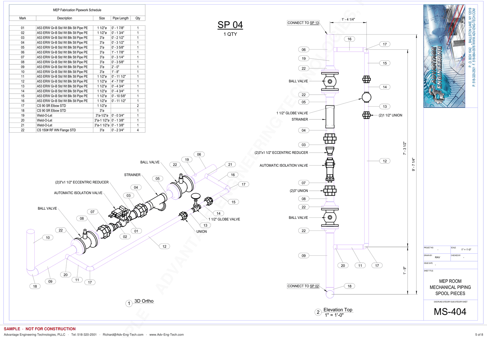
Once the conflicts are resolved, the schematic becomes buildable information. Plan views establish real routing and elevations. Piping isometric drawings establish geometry. Spool drawings carry exact cut lengths, weld locations, flange orientation and bolt-hole rotation, with a spool map and a bill of materials for each spool so the shop builds from one accurate set and the field installs in the right order.
That is the work AET performs. We do not produce P&IDs — those come from the A/E or engineering firm on the project. We review them, resolve what has to be resolved, and produce the fabrication-level deliverables that come after.
Where We Have Done This Work
- Hospitals and healthcare facilities
- Industrial process plants
- Commercial mechanical rooms
Frequently Asked Questions
Does AET create P&IDs?
No. P&IDs are produced by the A/E or the engineering firm the owner has engaged. AET reviews the P&IDs supplied on a project and derives plan views, piping isometrics and spool drawings from them.
What is the difference between a P&ID and a piping isometric?
A P&ID is a schematic — it shows function and connectivity with no real geometry. A piping isometric shows actual geometry: routing, dimensions, elevations and orientation. You cannot fabricate from a P&ID; you can fabricate from an isometric and the spool drawings developed from it.
What happens if a conflict is found during review?
It gets documented and routed back through the contractor as an RFI before fabrication is released. Resolving it on paper costs a drawing revision. Resolving it after the spool is cut and welded costs material, shop time and schedule.
Can you work from P&IDs that are incomplete or still in progress?
Often, yes — but what can be released for fabrication depends on which information is still open. Areas that depend on unresolved items are held rather than fabricated on assumption, and we identify those up front so the sequence can be planned around them.
Pipe Spool Drawings and Fabrication Deliverables
Advantage Engineering Technologies, PLLC produces fabrication-level piping deliverables for mechanical contractors — spool drawings, spool maps, bills of material and the coordinated plan views behind them, developed from the project’s P&IDs and approved submittals.
View or download sample pipe fabrication drawings: Pipe Fabrication Sample | Phone: (518) 320-2501