Modern commercial and industrial construction leaves no room for guesswork. Tight ceiling spaces, congested mechanical rooms, and aggressive schedules demand fabrication-ready HVAC drawings that eliminate field conflicts and support fast, predictable installation.
On commercial projects, the mechanical contractor is typically the last trade in — which means every upstream conflict lands on your schedule and your budget. Contractors who rely on traditional 2D drawings or uncoordinated design models often face:
- Change orders caused by late-stage clashes
- Costly field rework
- Delayed inspections
- Material waste
- Labor overruns
HVAC Fabrication Drawings, supported by full BIM coordination, solve these problems by delivering precise, build-ready documentation that fabricators and installers can trust.
At Advantage Engineering Technologies, we specialize in producing LOD 400 fabrication models, piping spool drawings, duct fabrication sheets, and fully coordinated HVAC shop drawings that streamline installation and reduce project risk.
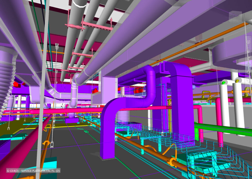
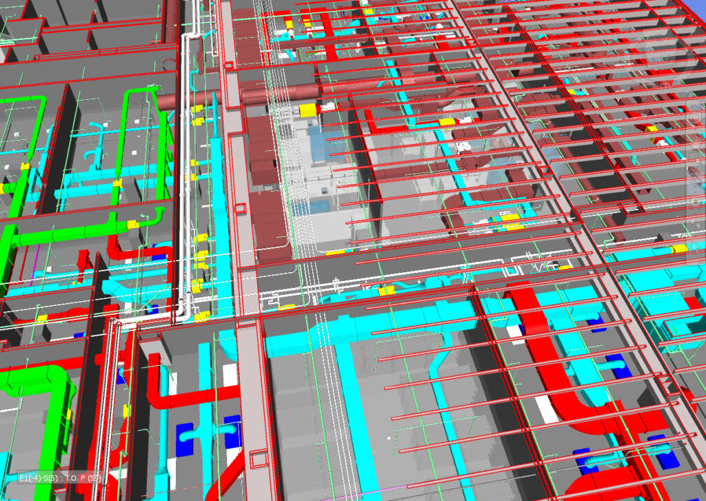
AET BIM model showing congested above-ceiling MEP coordination — the type of complexity that demands fabrication-ready documentation.
What Are HVAC Fabrication Drawings?
HVAC Fabrication Drawings are detailed, production-ready documents used to manufacture ductwork, piping systems, fittings, supports, and mechanical assemblies before they reach the job site.
Unlike design drawings, fabrication drawings include:
- Exact dimensions and cut lengths
- Material specifications and gauge/thickness
- Joint types (TDC, S&D, welded, grooved, threaded)
- Hanger spacing and rod sizes
- Spool break points and numbering
- Fitting callouts and fabrication notes
- Elevation tags and section cuts
- Sleeve and penetration locations
- Equipment connection details
- Field-fit allowances and tolerances
These drawings are developed directly from LOD 400 fabrication models, ensuring that every component is coordinated, clash-free, and ready for prefabrication.
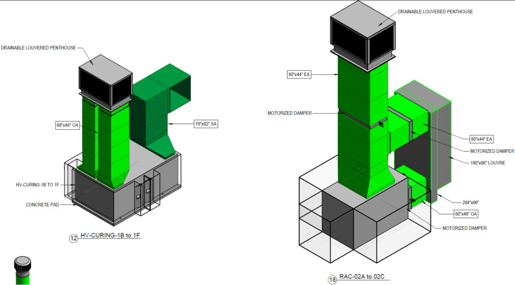
AET LOD 400 ductwork isometric drawing — production-ready fabrication documentation developed directly from a coordinated BIM model.
What Makes a Drawing Truly “Fabrication-Ready”?
Contractors often receive drawings labeled “fabrication-ready” that still require field adjustments. True fabrication documentation must include:
- Exact Manufacturing Dimensions
- Center-to-center lengths
- End-to-end lengths
- Fitting throat and heel dimensions
- Pipe cut lengths with allowances
- Hanger & Support Coordination
- Rod lengths
- Insert locations
- Trapeze spacing
- Structural attachment points
- Spool Drawings
- Spool numbers and break logic
- Weld maps
- Bill of materials
- Assembly views
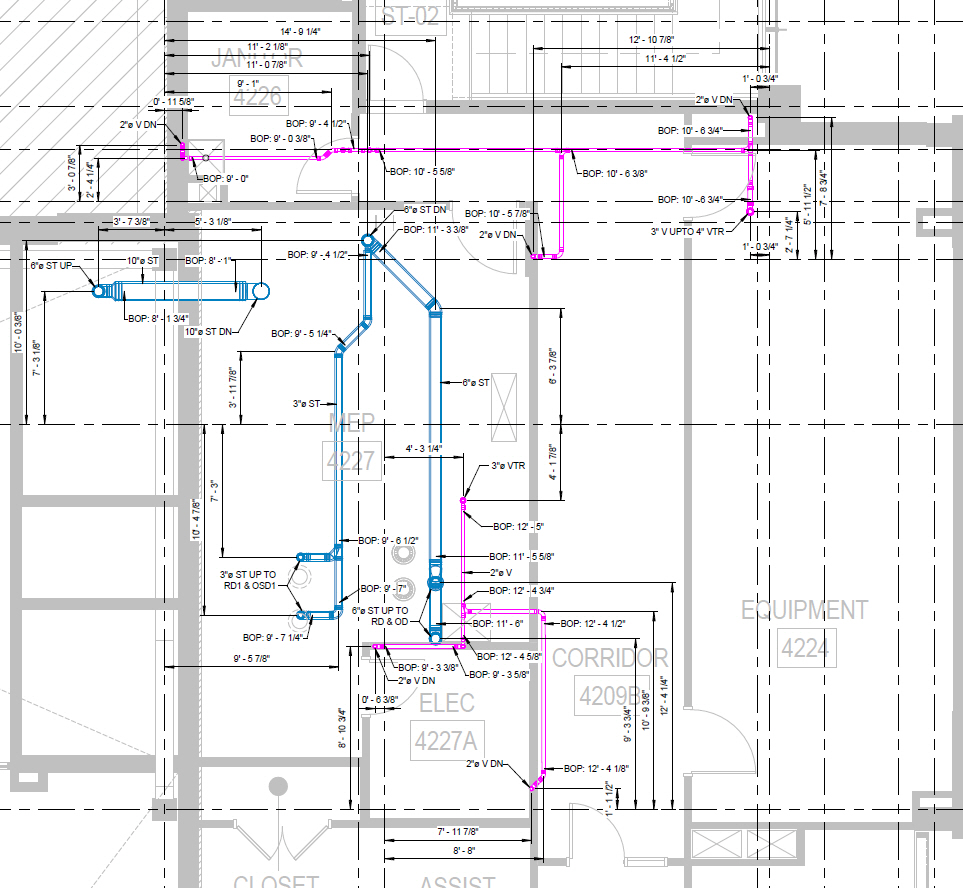
AET gravity piping shop drawing showing spool numbering, break logic, bill of materials, and installation dimensions.
- Tolerance & Clearance Requirements
- Access zones
- Maintenance clearances
- Fire/smoke damper access
- Equipment service envelopes
- CAM-Ready Output
For sheet metal and piping fabrication shops using Vulcan, CAMduct, TigerStop, plasma cutting tables, and CNC pipe fabrication equipment, the model must export cleanly to their equipment.
When these elements are present, the drawings can be fabricated with confidence — no field measuring, no guesswork, no rework.
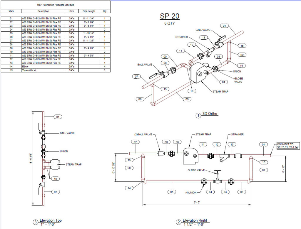
AET spool piece piping — prefabricated mechanical assembly produced directly from LOD 400 spool drawings.
Why BIM Coordination Is Critical for Fabrication Drawings
Commercial HVAC systems must coexist with structural steel, architectural ceilings, electrical conduits, plumbing systems, fire protection piping, and IT and low-voltage systems. Without BIM coordination, conflicts are inevitable.
Common Field Conflicts Eliminated by BIM
- Duct mains hitting beams
- Pipe slopes conflicting with ceiling heights
- VAV box access blocked by lighting or framing
- Hangers clashing with sprinkler mains
- Equipment clearances violated
- Sleeves misaligned with structural openings
Through automated clash detection and multi-disciplinary coordination meetings, these issues are resolved digitally — long before installation.
AET open-roof MEP BIM model showing the full multi-trade coordination complexity that must be resolved before fabrication can begin.
Benefits of BIM-Coordinated HVAC Fabrication Drawings
- Reduced Rework & Change Orders
Clash-free models eliminate costly field modifications.
- Faster Installation
Prefabricated duct and piping assemblies arrive ready to install.
- Accurate Material Takeoffs
LOD 400 models produce precise quantities for procurement.
- Improved Labor Productivity
Installers follow clear, unambiguous drawings.
- Better Project Predictability
Coordinated models reduce schedule risk and inspection delays.
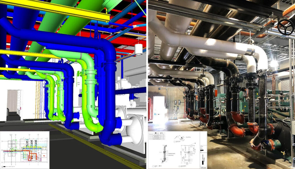
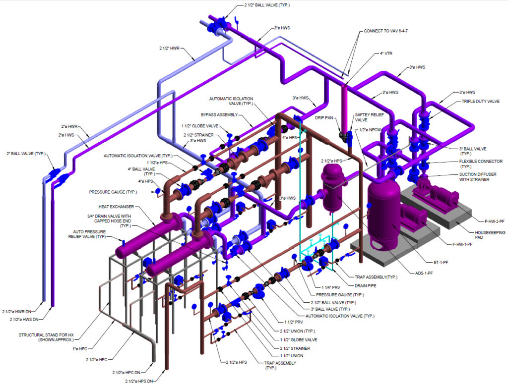
AET LOD 400 chiller plant BIM model — coordinated prior to installation.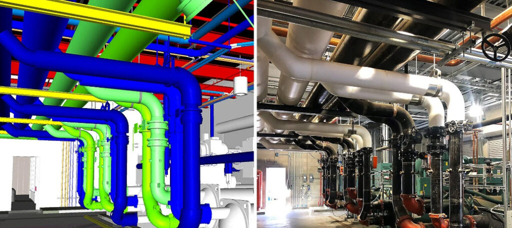
The same chiller plant as-installed — a direct result of fabrication-ready BIM coordination.
The Role of LOD 300, 350 & 400 in HVAC BIM Modeling
LOD 300 – Design Intent
- General routing
- Approximate sizes
- Basic equipment locations
LOD 350 – Coordination Level
- Exact routing
- Clearances
- Inter-disciplinary coordination
- Clash resolution
LOD 400 – Fabrication Level
- Manufacturer-specific components
- Exact dimensions
- Hanger modeling
- Spool-ready assemblies
- CAM-exportable geometry
Contractors who want true prefabrication must work from LOD 400 models — not LOD 300 design models.
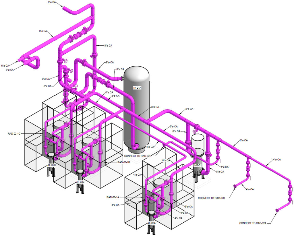
AET compressor room isometric drawing — LOD 400 fabrication-level geometry with exact dimensions, hanger modeling, and spool-ready assemblies.
3D Modeling for HVAC Systems: Why It Matters
3D HVAC modeling provides a digital twin of the final installation, enabling:
- Accurate visualization
- Early conflict detection
- Precise hanger and support layouts
- Reliable quantity takeoffs
- Prefabrication sequencing
- Improved field coordination
With 3D modeling, installers know exactly what they’re walking into — no surprises.
HVAC Coordination Drawings: The Blueprint for Installation
Coordination drawings are produced after all trades have resolved conflicts. They include:
- Duct and pipe routing with elevations
- Equipment placement and access zones
- Structural penetrations and sleeve locations
- Hanger and trapeze layouts
- Section cuts and detailed views
- Ceiling coordination and plenum constraints
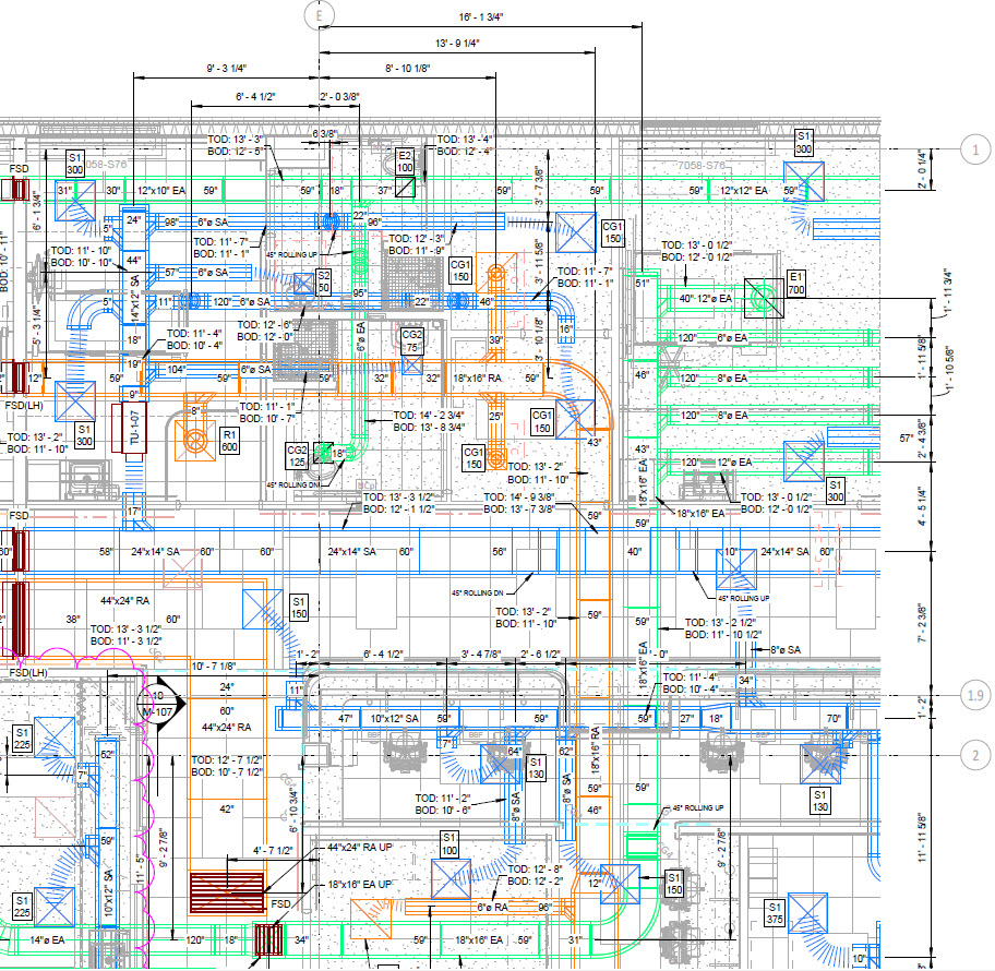
Harrison Hospital duct shop drawing — fully coordinated HVAC fabrication documentation produced by AET for a complex healthcare project.
Fabrication-Ready HVAC & Piping Drawings Workflow
- Design Review
Understand design intent, equipment submittals, and project constraints.
- BIM Model Development
Model mechanical systems using Revit, AutoCAD MEP, or Fabrication CADmep.
- Clash Detection
Run Navisworks or BIM 360 clash tests against all trades.
- Coordination Meetings
Resolve conflicts with structural, architectural, plumbing, electrical, and fire protection teams.
- LOD 400 Fabrication Modeling
Convert coordinated layouts into fabrication-level geometry.
- Shop Drawing Production
Generate duct fabrication sheets, piping spools, hanger drawings, and installation plans.
- QA/QC Review
Verify dimensions, tolerances, hanger spacing, and fabrication logic.
- Fabrication & Installation
Deliver CAM-ready files and installation drawings to the field.
Why Contractors Choose Advantage Engineering Technologies
Contractors rely on AET because we deliver:
- True LOD 400 fabrication models
- Accurate HVAC Fabrication Drawings
- Piping spool drawings with weld maps
- Duct fabrication sheets ready for CAM
- Clash-free coordination models
- Rapid turnaround for fast-track projects
- Clear, installer-friendly documentation
- As-built models for turnover packages
Whether your project is in Ballston Lake, NY or anywhere in the United States, our goal is simple: reduce risk, eliminate rework, and help your team install with confidence.
AET LOD 400 mechanical room isometric shop drawing — the level of precision and detail contractors depend on for successful prefabrication and installation.Conclusion
As mechanical systems grow more complex, HVAC Fabrication Drawings and BIM-coordinated models have become essential for successful project delivery. Contractors who rely on fabrication-ready documentation experience fewer conflicts, faster installation, and more predictable outcomes.
If you need accurate, coordinated, and fabrication-ready HVAC or piping drawings, contact Advantage Engineering Technologies today to discuss your project requirements and see how fabrication-ready BIM documentation can reduce risk and accelerate your schedule.