- P.O. Box 1042 Ballston Lake, N.Y. 12019-1042
- Mon–Fri 9:00 AM – 6:00 PM EST
- 518-320-2501

Opal Sands Resort, Clearwater Beach, Florida
General contractor: Moss Construction | AET scope: plumbing BIM modeling, multi-trade coordination, clash resolution, and construction documentation
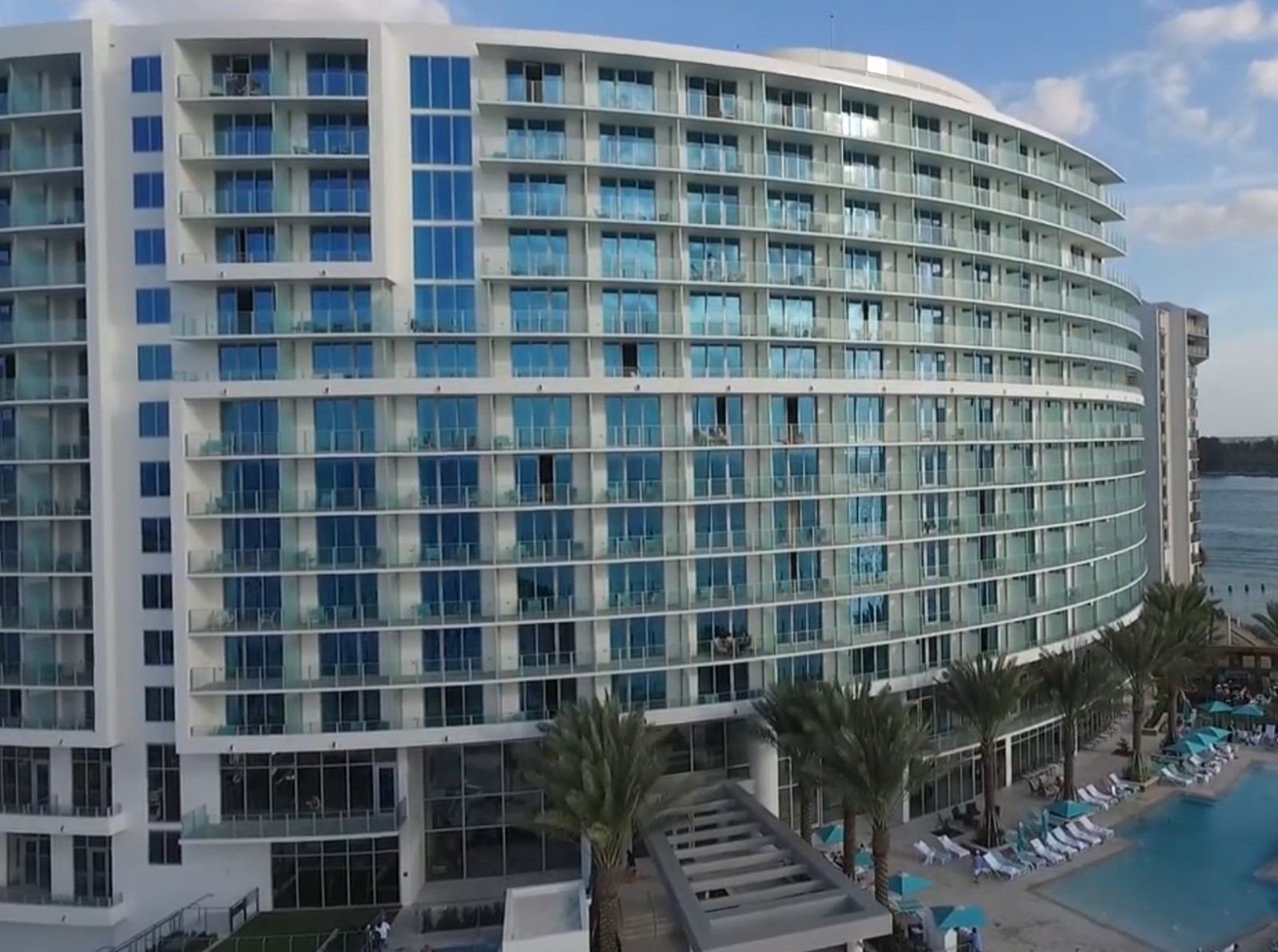
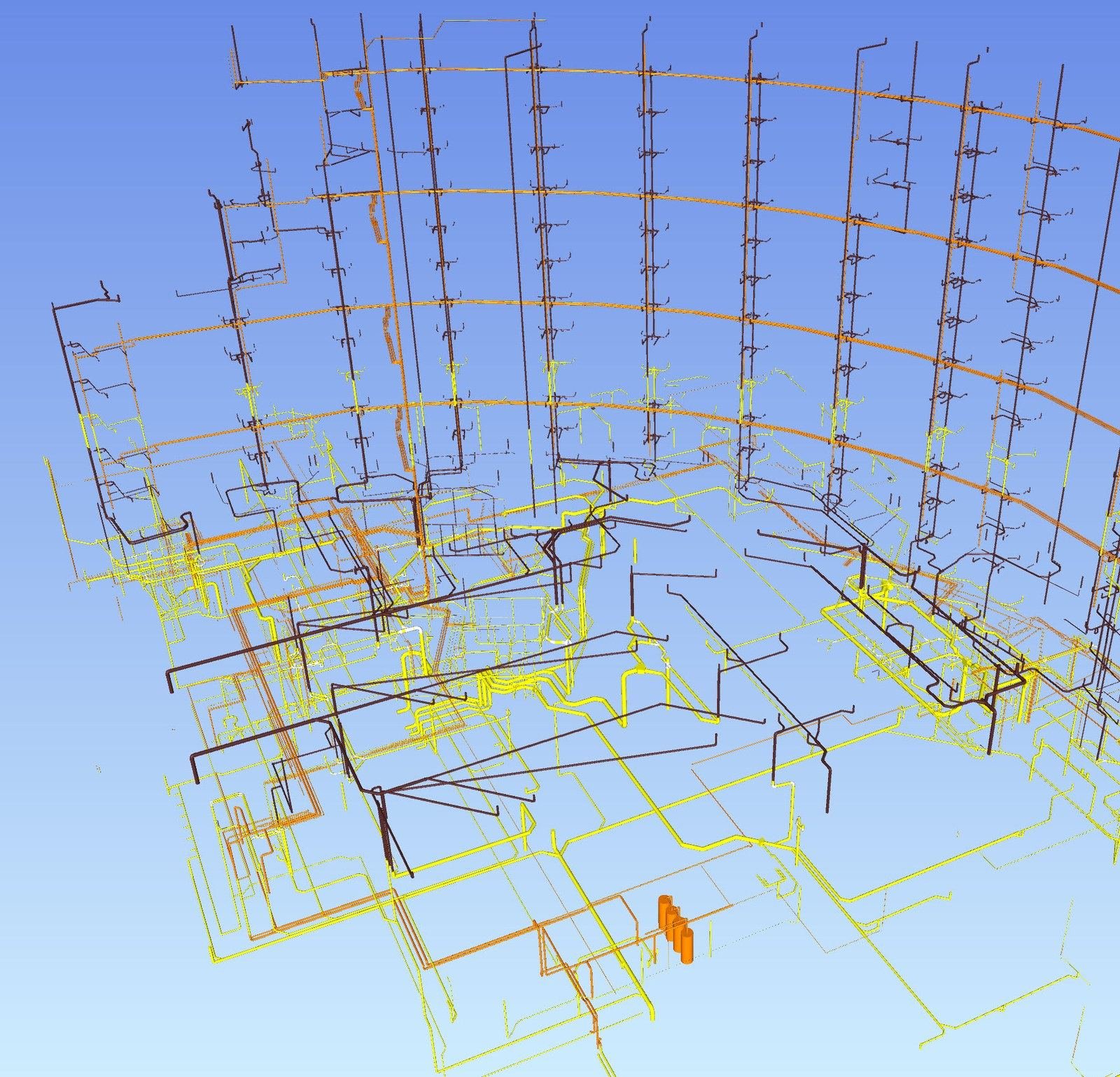
The Opal Sands Resort is a luxury 15-story, 230-room oceanfront hotel on Clearwater Beach, Florida, built by Moss Construction. Its signature curved architectural footprint makes for a striking building, and a demanding one to coordinate. The curve produces non-standard ceiling cavities on every floor, forcing plumbing, HVAC, electrical, and fire protection into ceiling spaces with almost no slack. Add multiple restaurants and commercial kitchens, a large pool deck and spa, and high-density guestroom riser stacks, and the project left no room for field improvisation: every system had to be proven out digitally before a single hanger went in.
Advantage Engineering Technologies provided full plumbing BIM modeling and coordination for the project: domestic water, sanitary, vent, and storm systems modeled at LOD 300/350, plus commercial kitchen plumbing, pool deck and spa integration, and vertical riser coordination against HVAC, electrical, and structural. AET ran clash detection and resolution in Navisworks, produced sleeve and penetration drawings, supported coordination meetings through the construction cycle, and delivered final coordinated plumbing layouts for installation.
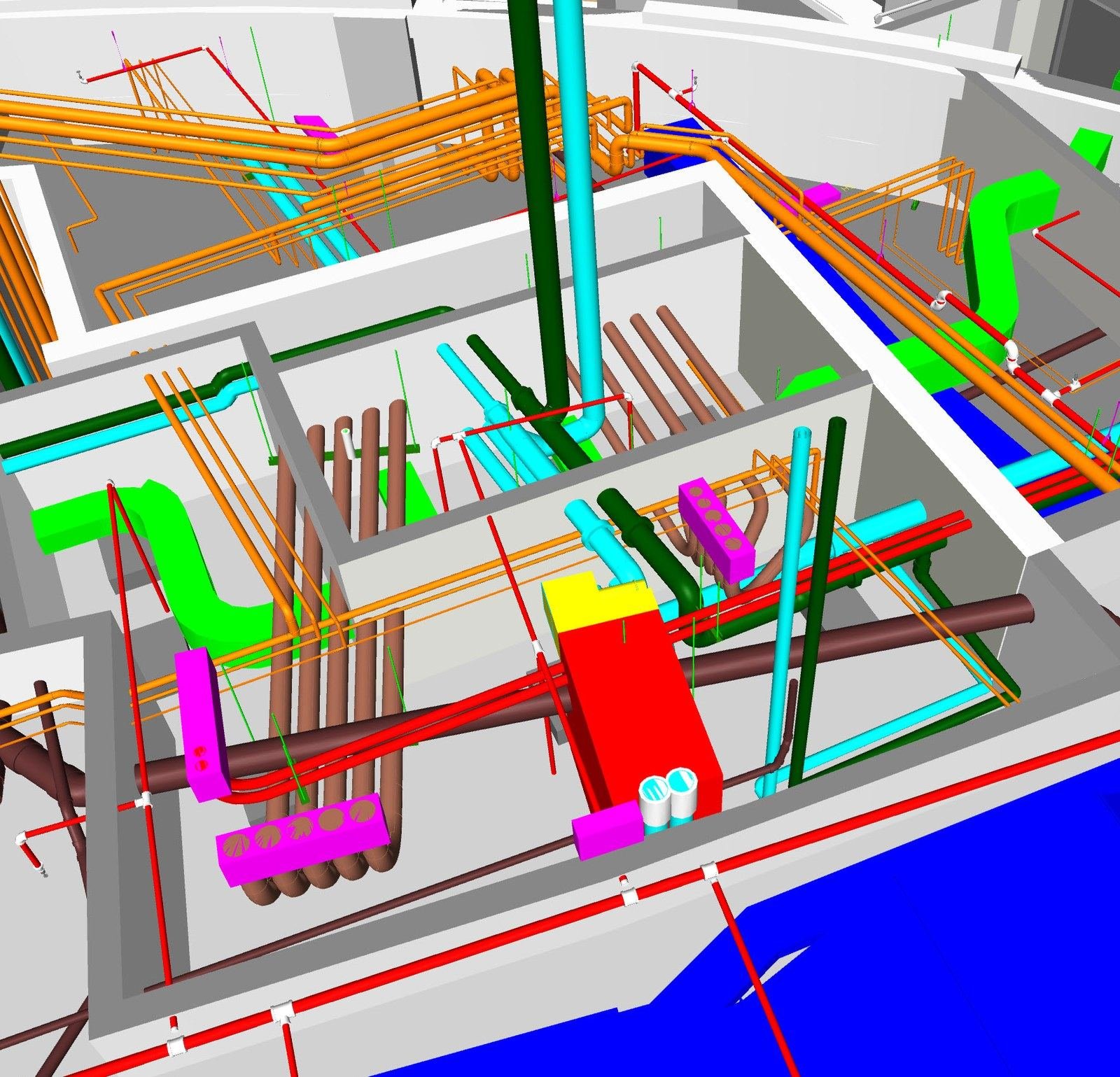
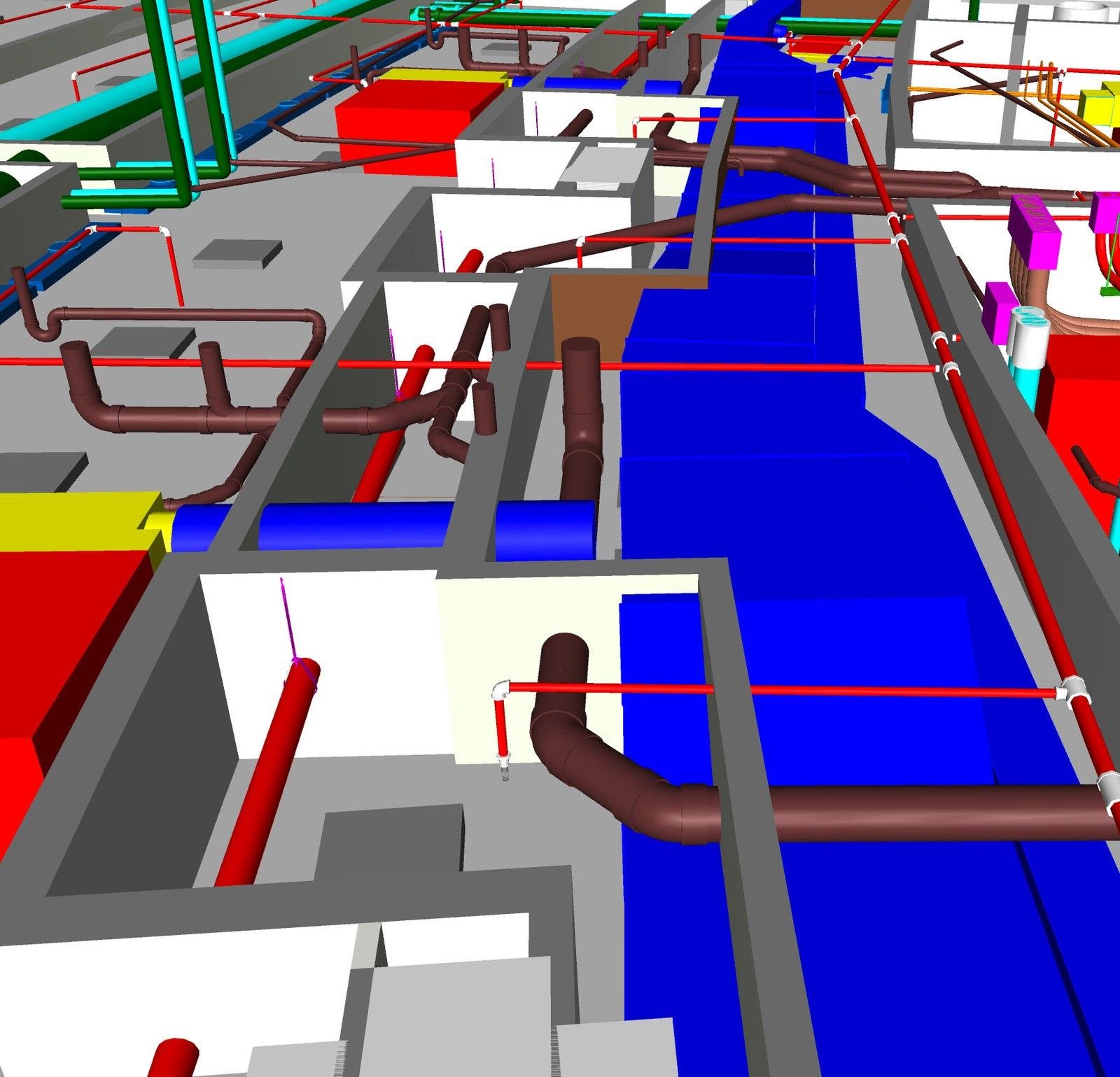
The curved building geometry meant ceiling cavities changed shape as they wrapped the floor plate. Routing that worked in one bay failed two bays down. Plumbing had to share these compressed spaces with ductwork, hydronic piping, and fire protection mains, and still maintain slope on gravity lines. In the view below, domestic water bundles, sanitary, hydronics, and ductwork all negotiate the same cavity along the building’s curve.
Each guestroom stack carried domestic cold water, domestic hot water, hot water recirculation, sanitary, vent, condensate, and fire protection drops: seven-plus systems repeating floor after floor for 15 stories. A fraction of an inch of misalignment at one floor compounds into an unbuildable shaft ten floors up, so every stack was modeled and coordinated to hold clearances and installation feasibility for the full building height, including the sanitary and vent drops concealed inside guestroom partitions.
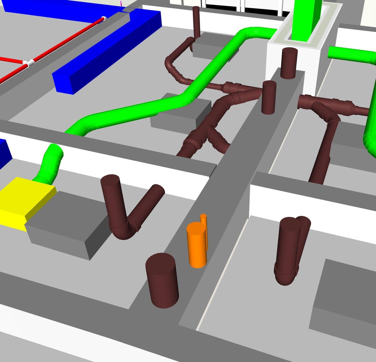
Serving 230 guestrooms plus multiple restaurants and bars, with grease waste, indirect waste, floor sinks, and high-capacity sanitary lines, meant large-diameter collecting mains that had to hold continuous slope while threading beneath duct mains and around fire protection. At that pipe size there is no nudging things in the field; the routing either works in the model or it doesn’t work at all.
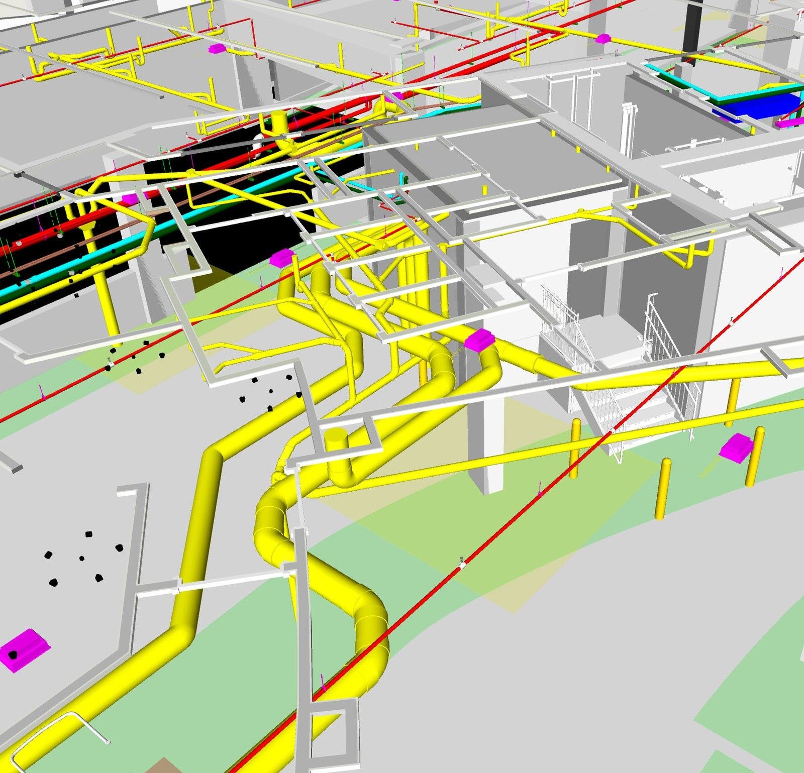
Below the tower, the parking level received the building’s storm and sanitary discharge into large overhead mains routed through the garage structure to the site connections. These runs were coordinated against fire protection mains, structural framing, and the clearance envelopes of the parking level itself, with the pool deck and spa systems above adding deck drains, storm piping, and overflow routing over post-tensioned slab zones, where every penetration had to be located precisely and locked in before the deck was poured.
Moss Construction ran rapid coordination cycles to hold the build schedule. Coordination turnaround was measured in days, not weeks; the model had to stay ahead of the crews.
AET built a complete plumbing model at LOD 300/350, with actual pipe sizes, slopes, elevations, clearances, equipment connections, riser locations, and sleeve locations, and coordinated it against every other trade: HVAC ductwork and piping, electrical conduit banks, fire protection mains, structural beams, PT slabs, shear walls, and architectural soffits and ceiling drops.
Clash detection ran in Navisworks through repeated coordination cycles, resolving hard clashes (pipe vs. beam), soft clashes (clearance violations), access conflicts at cleanouts, valves, and equipment, and routing congestion in the guestroom corridors. Conflicts were caught and resolved in the model instead of the field.
From the coordinated model, AET produced sleeve and penetration drawings for guestroom risers, mechanical rooms, kitchen areas, the pool deck, and vertical shafts, then delivered construction-ready documentation: coordinated plumbing plans, riser diagrams, detailed sections, installation drawings, and as-built markups where required.
The Opal Sands Resort opened on schedule and remains one of Clearwater Beach’s flagship properties, built on plumbing systems that were fully resolved before installation began. Moss Construction’s own project page is at moss.com/projects/opal-sands-resort.
AET provides fabrication-level plumbing and mechanical BIM services to contractors across the U.S. and Canada, from LOD 300/350 coordination models through spool sheets, BOMs, and shop drawings. If your next project has tight ceilings, dense risers, or a schedule that can’t absorb field rework, contact AET to discuss your scope. See also our MEP coordination drawings and sample drawings.